
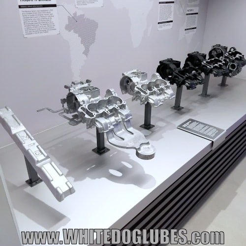
How are motorcycle crankcases made? The crankcase is an important and often overlooked part of a motorbike engine. As well as housing the crankshaft it helps control oil flow around the engine, get rid of heat and is often used as a ‘stressed member’ for the frame.
Note – A ‘Stressed Member’ is a part of the bike (other than the chassis) that’s used as part of the frame.
Crankcases are often used as stressed member join the front and rear of the bike, instead of the more conventional frame bars that go under the engine.
This means the crankcase absorbs the twisting forces of cornering and braking.
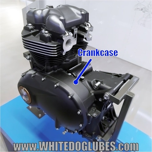
Location of the crankcase in a Triumph engine
The crankcase is the large metal casing that sits just below the cylinder barrels. It’s primary job is to house the crankshaft.
Main functions of the crankcase
- Housing the Crankshaft: The crankcase holds the crankshaft in the correct position using high precision main bearing journals.
Note – A ‘bearing journal’ is a smooth surface that the bearing sits in.
The crankcase also converts the up and down force of the pistons into rotational motion without flexing.
- Housing the Gearbox and clutch: Kind of self explanatory really!
- Engine Oil Reservoir: The crank case houses the internal oil channels that route the oil directly to crankshaft bearings, transmission gears, cylinder head and other vital engine parts.
- Structural Stressed Member for the Frame: The crankcase acts as a load bearing bridge in the frame structure on some bikes, absorbing braking and cornering forces (and often serving as the mounting point for the rear swingarm pivot).
The crankcase also has several secondary functions like managing the pressure created by the bottom of the pistons, mounting various system parts (e.g. starter motor, generator and oil pump) and switches (oil pressure switch etc), engine heat dissipation, environmental protection (it keeps dirt and water out of the engine and stops oil escaping) and it helps to reduce noise and vibration from the engine.
Stage 1: Obtaining the aluminium alloy
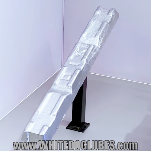
Example of the aluminium alloy ingot used to make the crankcase
Note – Aluminum alloy is pure aluminum mixed with specific elements like silicon, copper and magnesium to transform soft, light metal into a rock-hard, heat-resistant structural component.
The 1st step in manufacturing a crankcase is to get the aluminium alloy to make the case. This metal is normally very high quality but, depending on the use (e.g. if the crankcase isn’t being used as a stressed member) it can contain recycled metals.
Note – While everyday engine covers and some crankcases can use high-purity recycled alloys, primary structural crankcases use ultra clean, virgin alloys that are heat treated so they can act as a load bearing spine for the motorcycle frame.
Stage 2: High pressure molding
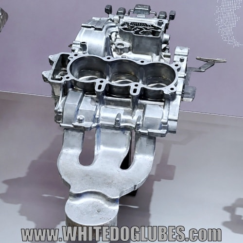
A rough, unmachined upper motorcycle crankcase fresh out of the mold.
Note – The odd bits of metal on the bottom and right side of the crankcase are ‘mold flashing’ which is the thin bits of excess metal that squeezes out from between the two halves of the mold during casting.
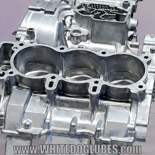
Close up of a motorbike crankcase just out of the mold showing the rough edges.
Molten aluminum is injected under high pressure into steel dies (molds) to form the basic shape of the crankcase (including rough cylinder sleeves and internal reinforcing ribs).
Stage 3: Deburring (removing excess metal) and painting
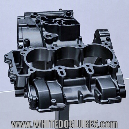
A deburred, shot blasted and painted (powder coated) top crankcase.
Note – Powder coating is a hard wearing finish where electrically charged dry paint powder is sprayed onto the metal crankcase then baked in an oven.
The heat melts the powder into a smooth, tough, plastic like skin that resists scratches and heat.
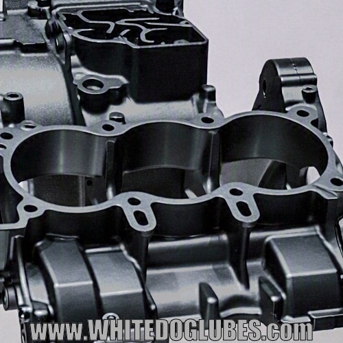
Close up of the rough edges of the painted crankcase.
Excess mold flash (metal overspill) is removed and the casting undergoes shot blasting and painting.
Applying paint at this stage protects the outer casing without risking paint contamination on precision machined internal surfaces or gasket faces.
Note – Triumph use a manufacturing process of ‘paint 1st, machine 2nd’ for crankcases (this process is also used by some other manufacturers like Yamaha, BMW, Ducati, Harley Davidson, KTM and Royal Enfield).
Other manufacturers machine 1st and paint 2nd.
Stage 4: Primary and secondary CNC machining
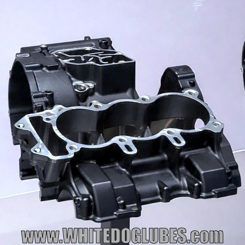
A machined upper crankcase showing the now clean edges where cylinder barels, engine casings etc will be attached.
Note – CNC stands for Computer Numerical Control.
In simple terms it means a computer converts a digital design into numbers and coordinates, which then automatically controls the movement of heavy cutting tools (like mills, lathes and drills) with extreme precision.
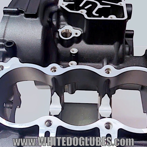
Close up of the machined upper crankcase showing the clean edges.
The casing is mounted on multi-axis CNC machine which then smooths, cuts, drills and cleans any rough edges where other parts (e.g. cylinder barrel) will be mounted.
The casing undergoes 2 different machining processes (primary and secondary).
Purpose of primary machining:
- Milling the primary flat mating faces (cylinder barrel, engine casing faces etc)
- Milling the crankcase split line
- Establishing specific points on the casing for subsequent machining
Purpose of secondary machining:
- Line boring (drilling) of crankshaft and gearbox bearing seats
- Drilling of oil passages and pathways
- Starter motor, engine side cases, cylinder (and anything that needs bolting on) mounting holes are drilled and thread tapped
Note – Like several internal components (such as camshaft caps and followers), motorcycle upper and lower crankcase halves are line bored together at the factory.
Because upper and lower crankcases are bolted and torqued together for line boring, and the tolerances for line boring are measured in microns, most manufacturers only sell crankcase halves as a matched pair.
They do it this way as crankcases that are not line bored together are unlikely to ever match up perfectly which often results in excessive vibrations, oil leaks and engine failure.
Stage 5: Wash, final deburr and CMM quality inspection
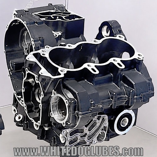
A complete upper and lower crankcase ‘pair’ showing the clean mating surfaces and line bored holes.
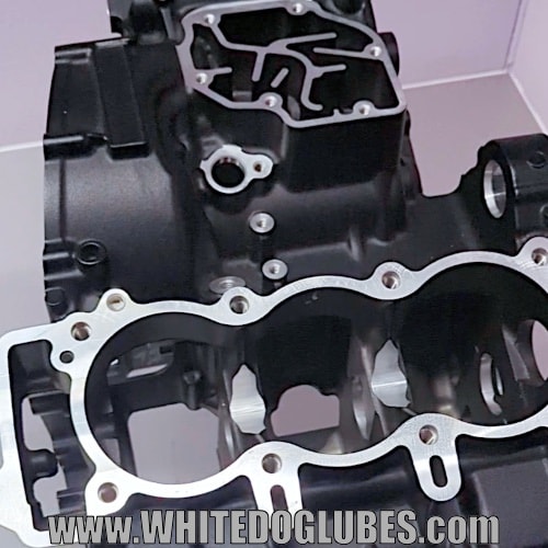
Close up of the completed crankcase matched upper and lower ‘pair’ (from a Triumph Speed Triple) .
The crankcase undergoes high pressure ultrasonic cleaning to flush out any metallic debris and cutting fluid from internal oilways followed by final deburring.
The crankcase is then quality verified and checked on a Coordinate Measuring Machine (CMM) before joining the engine assembly line.
Note – A CMM (Coordinate Measuring Machine) is an ultra precise digital measuring system.
It uses a tiny touch probe or laser to map a part’s exact dimensions, ensuring every engine component perfectly matches the original factory design down to the micron.
Note – The pictures used here were taken on a trip we made to the Triumph Factory Visitor Experience.
Sources / Thanks to / Useful sites:
Triumph – For the Factory Experience Exhibition, well worth a visit!
MCNews.com Got a bit of info from their review.
If you’ve got any questions, comments or suggestions please feel free to leave them below 🙂
Keep up to date by joining us on our social media pages:


Disclaimers:
The information provided on this page is ‘to the best of our knowledge’ and should not be taken as 100% accurate!!
To keep this page as a free resource for people to use, there are affiliate links (mainly Amazon) throughout the article. These affiliate links help maintain the cost of running this blog (basically, if you visit Amazon through one of the links and buy something, we make a few pence!).
Leave a Reply